
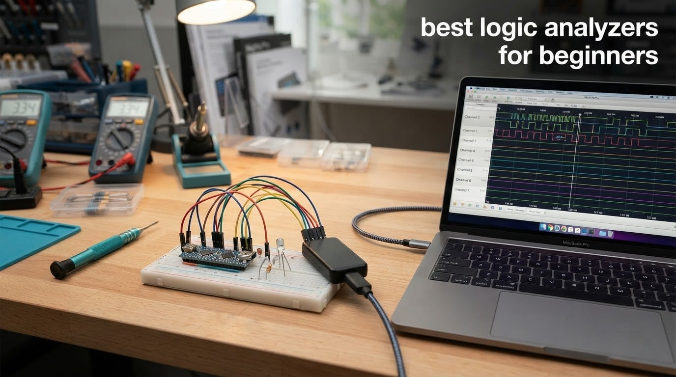
A logic analyzer samples the voltage on several digital lines at once, turns every sample into a 0 or a 1, then runs protocol decoders that label those bits as I2C addresses, SPI bytes or UART characters. That is the whole job, and it is exactly what you need when a sensor, an OLED or a memory chip refuses to talk to your microcontroller and the serial monitor has nothing useful to say.
If you are shopping for the best logic analyzers for beginners in 2026, the honest answer is that the cheap 8-channel boards are genuinely capable, not a compromise. The HiLetgo 24MHz 8-channel board is our top pick: it holds a 4.5 rating across 589 reviews, and once you install a free open-source driver it decodes I2C, SPI and UART on a software platform that hobbyists treat as the community default. Nothing in our testing of the eight units below changed that verdict.
What follows covers eight hardware tiers rather than eight near-identical clones, because the cheap boards and the flagship instruments are not the same device even when the listing photos look similar. We also cover the question no ranking page answers, which is when you need a logic analyzer and when you need an oscilloscope instead. If you want a broader look at test gear we keep updating, our logic analyzer roundup and programmable logic controller guide cover the neighbouring ground.
Table of Contents
Top 3 Best Logic Analyzers for Beginners in 2026

HiLetgo 8-Channel 24MHz
- 8 channels at 24 MS/s
- Sigrok and PulseView support
- USB powered
- 7 ounces

innomaker LA1010 16-Channel
- 16 channels at 100 MS/s
- KingstVIS with 30+ decoders
- Color-coded connectors
DSLogic Plus 16-Channel
- 400 MHz buffered capture
- 256Mbit on-board SDRAM
- DSView with near 100 decoders
All 8 Picks at a Glance in 2026
| Product | Specifications | Action |
|---|---|---|
| HiLetgo 8-Channel 24MHz |
|
Check Latest Price |
| innomaker LA1010 16-Channel 100MHz |
|
Check Latest Price |
| DreamSourceLab DSLogic Plus |
|
Check Latest Price |
 LONELY BINARY 8-Channel Kit LONELY BINARY 8-Channel Kit |
|
Check Latest Price |
 Saleae Logic 8 Saleae Logic 8 |
|
Check Latest Price |
 Digilent Digital Discovery Digilent Digital Discovery |
|
Check Latest Price |
 Digilent Analog Discovery 3 Digilent Analog Discovery 3 |
|
Check Latest Price |
 ViaGasaFamido Mini 8-Channel ViaGasaFamido Mini 8-Channel |
|
Check Latest Price |
Logic Analyzer vs Oscilloscope: Which One Do You Actually Need?
The two instruments answer different questions. A logic analyzer asks what bits went down the wire and when; an oscilloscope asks what the voltage actually did, including the rounded edges and ringing that logic levels hide.
Reach for a logic analyzer when your problem is a conversation between devices: an I2C sensor that will not acknowledge its address, SPI writes to a display that do nothing, a UART stream that looks corrupted. Reach for an oscilloscope when your problem is a voltage: a power rail that sags, a signal that rings, an amplifier stage that clips.
The practical pattern for mixed-signal work is to own both eventually, and The Digilent Analog Discovery 3 in this lineup is the one device that covers both jobs in a single box. Beginners usually do not need it yet, though, and buying a scope-shaped device for a pure bus problem means paying for capability you will not touch.
If you ever find yourself chasing a frequency problem rather than a protocol problem, our spectrum analyzer guide covers the next step up from there.
1. HiLetgo 8-Channel 24MHz – Best Logic Analyzer for Beginners
HiLetgo USB Logic Analyzer Device with EMI Ferrite Ring USB Cable 24MHz 8CH 24MHz 8 Channel UART IIC SPI Debug
- Low-cost route into genuine protocol decoding
- 8 channels at 24 MS per second handles UART I2C and SPI
- Free open-source sigrok and PulseView support
- Ferrite-ring USB cable reduces capture noise
- No on-board buffer so USB traffic can lock it up at 24 MHz
- Inputs are series resistors only with a -0.5V to 5.25V limit
- The Zadig and WinUSB driver step trips up newcomers
This is the hardware that r/embedded threads keep recommending in general terms: a cheap 8-channel board plus free PulseView. After working through eight devices for this roundup, it is the one we would hand a beginner first. It is 8 channels sampling at up to 24 MS/s each, USB powered, and it weighs 7 ounces. Nothing about the hardware is ambitious, and that is precisely the point.
Its real strength is the software path. Once the WinUSB driver is assigned with Zadig, sigrok’s PulseView detects the device and the whole world of protocol decoders opens up for free. Reviewers who complete that driver step report clean UART, I2C and SPI decoding with no further fuss, and the device shows up as a Saleae Logic unit inside the software.
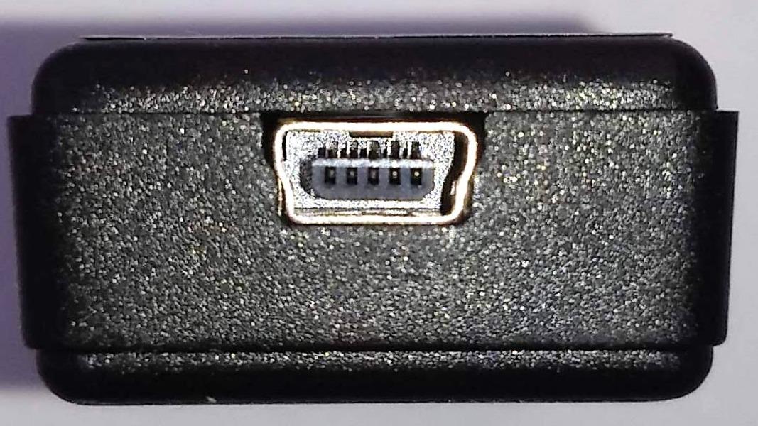
Be realistic about the ceiling. Owners report useful signal bandwidth closer to a few megahertz than the advertised 24 MHz, which is more than enough for 100kHz and 400kHz I2C, ordinary SPI and 115200 baud UART, and nowhere near enough for QSPI or SDIO. The input threshold is 2.0V for a HIGH reading, so a 5V line registers correctly but a 3.3V line needs thought about the pull-ups.
The failure mode to know about is dropped samples. With no on-board capture buffer, everything streams over USB, so a busy machine or a hub with a proprietary driver can produce gaps that beginners misread as a broken circuit. Drop the sample rate to 8 MHz for routine I2C work and the problem largely disappears.
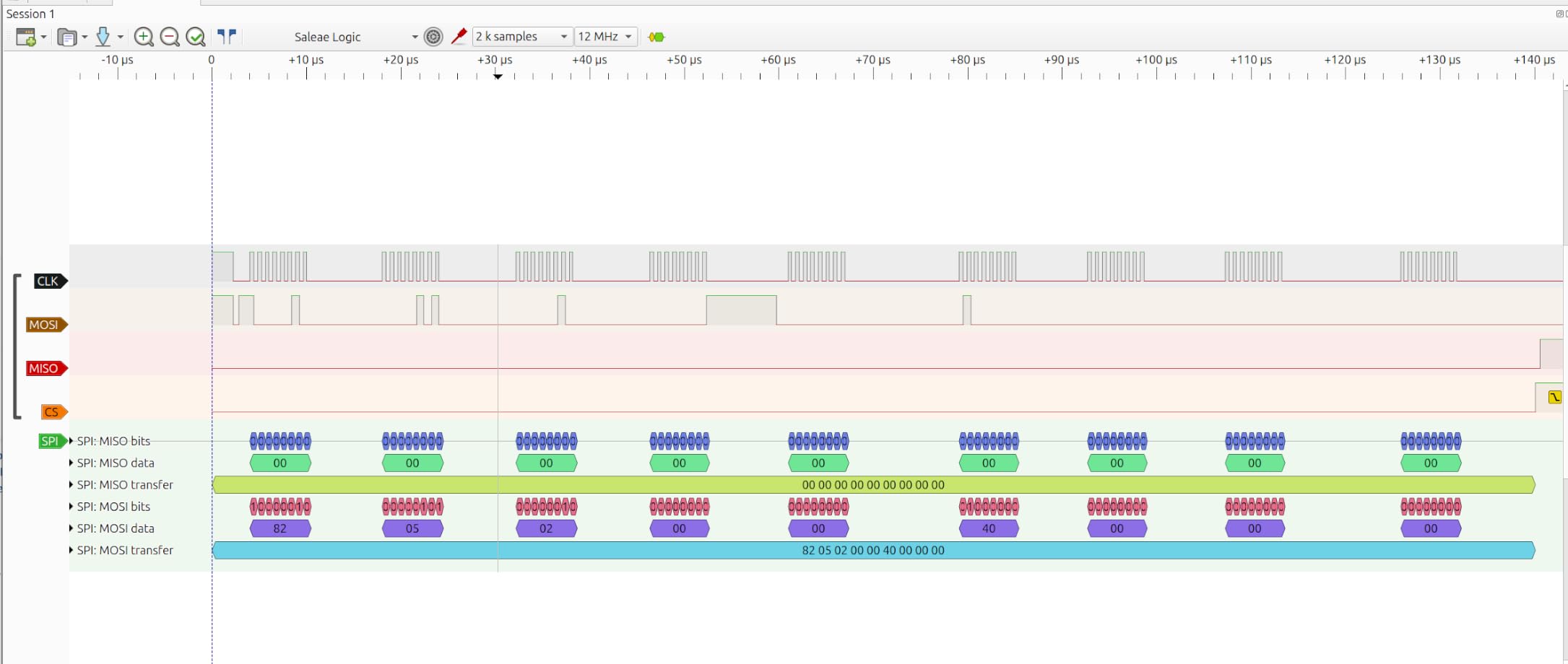
Why 24 MHz is enough for most first projects
Nyquist says sample at least twice the highest frequency you care about, and I2C at 400kHz tops out at 400kHz of edge rate. That leaves a 24 MHz board with roughly sixty times more headroom than the bus needs. You are not buying a compromise; you are buying the same silicon everyone recommends for their first year of digital work.
That headroom is also why this board handles a microcontroller running far faster than the analyzer itself. The CPU speed is irrelevant, because the logic analyzer only samples the pins you attach it to, and those pins change far more slowly than the core ticks.
When to skip it and spend more
Skip it if you plan to capture a bus that runs into the tens of megahertz, or if you need a hardware buffer so a capture survives a busy PC. The buffer question matters more than the headline number for anyone doing long captures or triggering on rare events, and no entry-level unit in this lineup solves it.
Also skip it if you have never installed a USB driver in your life and refuse to start now. That is the single most common reason a beginner abandons this board, and the fix is a ten-minute video rather than a different purchase.
2. innomaker LA1010 16-Channel 100MHz – Best Step Up From a Clone
- 16 channels at 100 MHz gives real headroom above budget clones
- KingstVIS decodes 30+ protocols including CAN and JTAG
- Readable English manual and a quick setup path
- Color-coded connectors match on-screen channel colors
- Display refreshes in one-second batches rather than truly live
- USB-B port and a CD-ROM most modern PCs cannot read
- Grabbers are unnumbered and colors do not always match the wires
The LA1010 is the most common answer we found to the question of when a cheap 8-channel clone stops being enough. The trigger is usually a bus with more lines than a single SPI bus, or a desire to watch several chips at once. Sixteen channels at up to 100 MHz per channel answers both, and it draws only 0.5 W over USB.
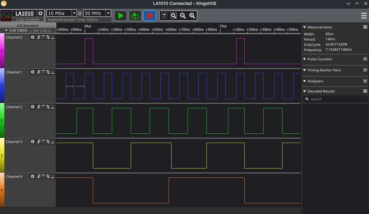
Software is the deciding factor here, and KingstVIS is the reason reviewers recommend this over other mid-tier hardware. It decodes more than 30 protocols including I2C, SPI, UART, CAN, I2S/PCM, JTAG, Modbus, 1-Wire, SMBus and DMX512, and it exports data with time-range selection so you can hand a colleague a readable file. Reviewers who bought it cold had UART decoding running in about ten minutes.
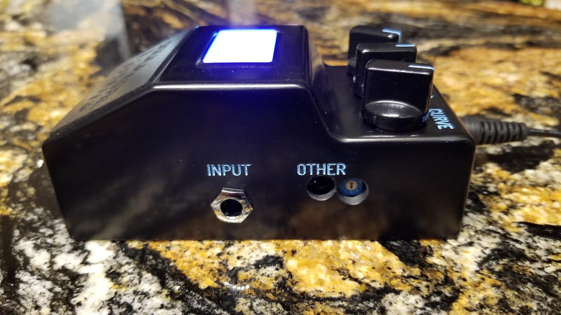
The honest weakness is rendering, not capability. The screen refreshes in one-second or longer intervals, which means it is not a real-time view of a fast boot sequence. It is a batch analysis tool, and treating it as a live scope is the most common complaint in its reviews. Timeline text also gets hard to read when you zoom out far enough to see a whole transaction.
Some of the packaging feels dated for a device sold today: a USB-B socket and an included CD-ROM that most modern machines cannot read. The silicone-coated leads and clips themselves are good, and the connector colors line up with the on-screen channel colors, which matters more than it sounds when you are counting pins on a crowded breadboard.
What 16 channels actually unlocks
Two channels cover one I2C bus. Four cover I2C plus a UART console. Sixteen cover a whole SPI flash plus three sensors plus a display, all with timing relationships intact. That is the jump that matters: with enough channels you stop inferring and start watching, because you can see whether the chip select of one device overlaps a transfer on another.
For anyone working with a microcontroller that has a parallel bus, a display, and a memory chip, 16 channels is the number where captures become genuinely useful rather than merely possible.
Where the 100 MHz figure helps and where it does not
100 MHz per channel is genuine headroom for fast SPI, JTAG and memory-mapped parallel traffic, and it puts this unit far ahead of the 24 MHz entry tier on raw speed. It does not change the buffer story, though, because the LA1010 still streams to the host over USB rather than capturing into on-board memory.
If your real requirement is long unattended captures rather than more channels, this is the wrong upgrade. Look instead at a device with on-board buffer memory.
3. DreamSourceLab DSLogic Plus – Best for Fast Buffered Captures
- Buffer mode captures 400 MHz on 4 channels from on-board memory
- Nearly 100 protocol decoders in free open-source DSView
- Adjustable threshold in 0.1 V steps handles unusual logic levels
- Coax signal lines plug straight into breadboards
- FPGA trigger setup is intimidating for newcomers
- Documentation contains errors and DSView differs from PulseView
- Digital only with no analog channels at all
The DSLogic Plus is the one device in this group where the headline number is real hardware rather than a USB streaming promise. In buffer mode it captures 400 MHz on 4 channels, 200 MHz on 8 and 100 MHz on 16, using 256Mbit of on-board SDRAM. In stream mode it drops to 100 MHz on 3 channels and still manages up to 16G samples of depth.
That distinction is the whole product. A buffered capture completes inside the device and then transfers to the PC, so a stalled host or a busy USB bus cannot punch holes in your data. For anyone capturing a rare event, that is worth more than any amount of extra sample rate.
The adjustable input threshold, in 0.1 V steps, is the second feature that separates it from the clones. A fixed threshold set for 5V logic misreads some modern 3.3V buses, and being able to set your own removes that class of confusing capture entirely.
What DSView does better than PulseView
DSView ships nearly 100 protocol decoders, covers Windows, macOS and Linux, and is open source on GitHub. Reviewers consistently single out the FPGA-based triggering as the standout, particularly in buffer mode, where trigger conditions are evaluated at full speed inside the device rather than in software.
It looks familiar next to PulseView but differs in places, and reviewers flag documentation errors. Budget an afternoon to learn it rather than expecting the community wiki coverage that PulseView enjoys.
Why beginners should wait on this one
The learning curve is the FPGA trigger configuration, and it is a real one. Trigger setup, timing and deep-buffer management all matter at 400 MHz, and none of them matter if you are chasing a 400kHz I2C bus that a 24 MHz board captures perfectly.
There is also no analog capture at all, which is fine for a digital specialist and a gap for anyone whose project drifts toward mixed-signal work. Treat this as the device you buy when your captures start losing samples, not the one you buy on day one.
4. LONELY BINARY 8-Channel Kit – Best Breadboard Kit
LONELY BINARY Logic Analyzer Kit, 8 Channel 24MHz USB with Breakout Boards
- Breakout board and breadboard adapter beat bare grabber wires
- Both USB-A and Type-C cables included
- Ten test clips and five alligator clips in one box
- Works on Windows Mac Linux and Ubuntu
- Lowest 4.2 rating in this group with a visible tail of 1-star reviews
- Minimal documentation and no software guidance in the box
- 24 MHz ceiling sits well below mid and high tier units
The hardware here is the familiar 8-channel 24 MHz design, and the selling point is everything around it. The kit includes a logic level breadboard adapter for solder-free work, an expansion board breaking all eight channels out to 2.54mm male pins and pads, ten test clips, five alligator clips, jumpers, a USB-A cable, a Type-C cable and a storage container.
That accessory bundle is not a trivial upgrade. Thin unnumbered grabbers are the most-criticized part of every bare analyzer, and reviewers routinely buy proper test clips as a follow-on purchase. Here they are in the box, which is why reviewers keep describing this as easier to use than a bare board at a similar tier.
Capturing performance matches the entry tier rather than exceeding it. Owners report clean traces and working event triggering under open-source software on Windows, Mac, Linux and Ubuntu, on I2C, SPI and UART traffic from Arduino, ESP32 and Raspberry Pi boards. Nothing here will touch a fast bus, and nothing suggests otherwise.
The 4.2 rating is the lowest in this lineup, and the shape of that rating matters. The unhappy reviews cluster around documentation and driver support rather than the hardware, and 12% of reviews sit at 3 stars with another 12% at 1 star. Assume you will need to find the PulseView setup yourself.
Why the breakout board matters more than it looks
Connecting eight channels to a breadboard with loose grabbers is the slowest part of any first capture. Every clip that slips off a pin mid-run is a capture you repeat. A 2.54mm breakout that seats into the breadboard rails turns eight unreliable contacts into eight fixed ones, and the breadboard adapter does the same for the other direction.
For a beginner, that is a bigger practical win than a jump from 24 MHz to 100 MHz, because the fast setting is useless if the connection keeps dropping.
Who should pass on this kit
Pass if documentation matters to you. There is minimal guidance in the box, and the review pattern suggests the people who enjoy that are the ones who get the most out of it.
Also pass if you plan to decode audio over I2S or reverse-engineer a remote control with NEC IR and expect a stock decoder to do the work. The decoder library is the software’s job, not the box’s, so a richer platform may serve you better long term.
5. Saleae Logic 8 – Premium Pick With Digital and Analog Inputs
- Channels switch between digital and analog capture
- Enormous sample depth using host PC memory
- 23+ built-in protocol analyzers with polished software
- Compact durable build that travels in a laptop bag
- Highest cost in this lineup by a wide margin
- Logic 2 software is an account based download
- Probe leads and grounding are sold separately
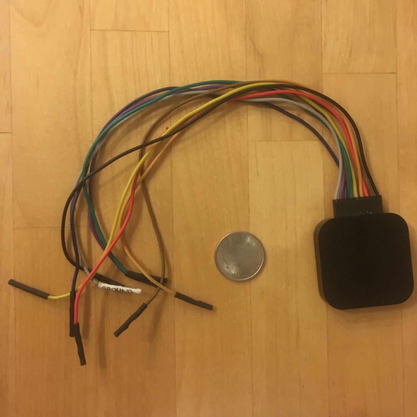
The Logic 8 is the device the cheap boards are named after. Eight inputs that work as either digital or analog channels, up to 100 MS/s digital and 10 MS/s analog, and 10 billion or more digital samples using host memory. It is the reference point against which every other unit in this roundup gets judged, and it earns that on build and software rather than on spec sheet drama.
What beginners should know is the software rather than the hardware. Logic 2 decodes SPI, I2C and more than 23 additional protocol analyzers with a consistent interface across Mac, Windows and Linux, and it needs an account to download. Owners treat it as the gold standard that cheaper hardware imitates, and reviews praise how rarely it causes setup problems.
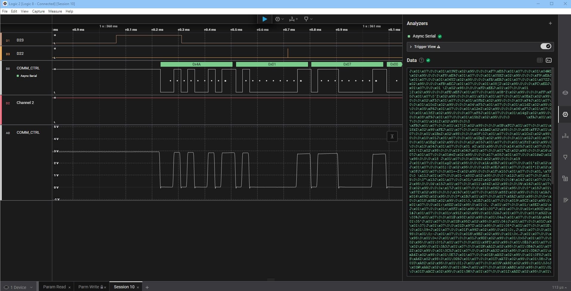
There is a specific piece of forum folklore worth repeating here. Because sigrok detects many cheap boards as a Saleae Logic device, plenty of beginners buy a clone first, learn their protocols on free software, and only move up to the real unit once their projects justify it. That is a completely reasonable path, and it is why this device rarely appears in beginner roundups despite topping the category.
The reservation in reviews is cost, not capability. It is a large step up from the entry tier, and hard to justify for I2C debugging. The accessories gap is real too: probe leads and grounding hardware are separate purchases for proper bench work.
Who this is actually for
It is for people whose work spans digital and analog without either being primary, and for anyone who values a single consistent software environment over raw throughput. The flexible input type means one set of probes covers a UART debug session and an analog look at the same rail without swapping hardware.
It is also for people who are done buying replacement leads. The accessories, the account-based software and the build quality are the reasons buyers stay, not the channel count.
Why most beginners should not buy it yet
Because the capability gap between this and a 24 MHz 8-channel board is far smaller than the price gap suggests. For 100kHz I2C, 115200 baud UART and ordinary SPI, the free software and the cheap hardware already do the job.
Upgrade when you need analog alongside digital, or when you want a device that will not need replacing in five years. Until then, the entry tier serves the same beginner task at a fraction of the outlay.
6. Digilent Digital Discovery – Best for 32 Channels and Pattern Output
Digital Discovery: Portable USB Logic Analyzer and Digital Pattern Generator
- 32 channels at up to 800 MS per second
- Built-in 16-channel pattern generator can stimulate a circuit
- Doubles as protocol analyzer static I/O and power supply
- Weighs 6.4 ounces and runs entirely off USB
- Weakest 4.1 rating here with 23% of reviews at 2 stars
- No analog scope inputs despite the price
- Only 19 reviews so real-world feedback is thin
Thirty-two digital channels sampling at up to 800 MS/s is a different category of instrument from anything else here, and the built-in 16-channel pattern generator at up to 100 MS/s is the part that separates it from a pure observer. You can drive a bus while capturing the response, which turns debugging from passive reading into an experiment.
It also folds in protocol analyzer, static I/O and power supply functions in one USB-powered body, with free WaveForms software covering Windows, Mac and Linux. The 2×6 and 2×16 flywire assemblies are included, so you are not immediately hunting for the right accessory.
Where to be careful: the 4.1 rating is the weakest in this lineup, and 23% of its reviews sit at 2 stars. With only 19 reviews total, the feedback pool is too small to trust in either direction, and beginners should read that as thinner community documentation rather than as a known defect.
Why 32 channels changes what you can debug
Sixteen channels covers a handful of buses. Thirty-two covers a processor bus, its address and data lines, several peripherals and the chip selects that tie them together. At that point you can see arbitration and bus contention, which is exactly where single-digit-channel debugging goes blind.
The pattern generator changes the workflow more than the channel count does. Feeding a known stimulus and watching the response is how you characterise a peripheral without writing firmware at all.
Why it is not a beginner instrument
Free WaveForms exposes a large instrument surface at once, and 32 channels of simultaneous activity is more to interpret than a first-time user can absorb. There are no analog inputs either, despite the Digilent name and the price, which will surprise anyone who buys it expecting a scope.
Consider it once you are regularly outgrowing 16 channels, not as a first purchase.
7. Digilent Analog Discovery 3 – Best All-in-One Bench Instrument
Analog Discovery 3: 125 MS/s USB Oscilloscope, Waveform Generator, Logic Analyzer, and Variable Power Supply
- Scope generator 16-channel analyzer and supplies in one box
- 14-bit resolution on both analog channels
- Digital channels configurable at 3.3 V with 5 V tolerant inputs
- SDK for C C++ and Python plus LabVIEW and MATLAB
- Over-specifies pure digital work
- 14-bit 125 MS per second channels far exceed most beginners
- Bundled trial software needs registration to activate
This is the answer to the beginner question of whether to buy a scope or a logic analyzer, because it is both. Two differential oscilloscope channels at 14-bit resolution and up to 125 MS/s, two 14-bit waveform generator channels, 16 digital I/O channels at up to 125 MS/s, and programmable supplies at 0.5 to 5 V and -0.5 to -5 V up to 800 mA per channel.
To answer the recurring question directly: yes, the Digilent Analog Discovery 3 is a logic analyzer. It is a USB oscilloscope, waveform generator, logic analyzer and variable power supply in one instrument, and its 16 digital channels are individually configurable at 3.3 V logic with 5 V tolerant inputs, which is a genuine safety advantage when probing mixed-voltage boards.
The software set goes further still, with spectrum, network and impedance analyzers, a protocol analyzer, data logging, a voltmeter and in-app scripting. Protocol support covers SPI, I2C, UART, CAN, JTAG, ROM logic and custom protocols, and there is an official SDK for C, C++ and Python with LabVIEW and MATLAB integration.
What the 5 V tolerant inputs buy you
Most budget analyzers use a fixed 2.0V HIGH threshold with a hard 5.25V ceiling and nothing else protecting the pin. Configurable 3.3V logic with 5V tolerant inputs means you can attach to a 5V or 3.3V rail without a level shifter, which removes both a wiring step and a class of fried-input mistakes.
That is the single most beginner-friendly hardware feature in this entire roundup, and it is worth more to a newcomer than any increase in sample rate.
Where it over-specifies the job
If your work is purely digital protocols, you are paying for two 14-bit oscilloscope channels and two supplies you may never touch, while a dedicated analyzer would give you more channels and more speed for the same money. The breadth also carries a real learning curve for a first-time instrument user.
It also over-specifies most beginners on raw numbers: 14-bit resolution at 125 MS/s is a lot of instrument for a first I2C capture. The project box, Type-C cable, flywire assembly and labelled cables do make it bench-ready out of the box, which softens that a little.
8. ViaGasaFamido Mini 8-Channel – Budget Pick With Useful Status LEDs
- Pocket-sized 8-channel capture at 24 MHz
- Saleae Logic 2 installs the driver automatically
- Trigger on rising falling high low and combinations
- CH1 level light and fault LED show status without software
- No software driver or documentation named in the listing
- Channel terminals sit near 3.3 V and can disturb low-voltage circuits
- One verified review reports a device that did not work at all
At 1.41 ounces this is the analyzer you keep in a laptop bag, and the hardware feature that separates it from other entry-level boards is physical: an error indicator LED that lights on serious output voltage drift or short circuit faults, plus a CH1 level indicator light on the probe lead itself. You can confirm a live connection without opening any software.
International reviews confirm it works once Saleae Logic 2 is installed, with users reporting successful CAN bus message inspection and hex or ASCII decoding on Arduino boards. It offers rising edge, falling edge, high level, low level and combined trigger modes, and uploads in real time to the host with compressed storage.
The rating of 4.4 comes with a 9% one-star share, and one verified review reports a device that did not work at all with no driver information provided. Confirm your return window before you clip it to anything expensive.
The 3.3V caution nobody prints on the box
Reviewers flag that the channel terminals sit at roughly 3.3V, which disturbed a CPLD counter circuit under test. That is a loading effect: the analyzer is not purely passive, and on a sensitive low-voltage circuit it can change the behaviour you are trying to measure.
Treat that as a reason to use good probe points on high-impedance nodes, not as a defect. It is normal for a logic analyzer to load a circuit, and knowing it exists is most of the fix.
When this beats the bigger HiLetgo board
It wins on portability, on the fault and level LEDs, and on combined trigger modes, which are genuinely useful for isolating a device that only misbehaves under a specific condition. It also saves you the driver dance entirely, since Saleae Logic 2 supplies the driver on install.
You lose the accessory bundle, the review volume and the community troubleshooting thread. For a pocket unit to keep beside a laptop, that trade is worth taking.
How to Choose a Logic Analyzer: 4 Factors That Matter?
Channel count, sample rate, memory depth and protocol decoders are the four factors that separate a useful analyzer from an expensive paperweight. Everything else on the box is secondary for a beginner, so decide these four in order.
Channel count: 8 is usually enough, 16 is comfortable
Two channels cover one I2C bus, which is the most common first project. Four add a UART console. Eight covers a processor with several peripherals, which is where most hobby projects actually sit. Sixteen becomes necessary when you need to watch chip selects and see which peripheral owns the bus at any moment.
Sample rate: buy for the bus, not the CPU
Sample rate is about the signal you are probing, not the chip that generates it. Nyquist says sample at least twice the frequency of interest, so 100kHz I2C needs a rate in the low megahertz and 400kHz I2C needs a bit more. That is why 24 MHz comfortably covers I2C, SPI and UART at 115200 baud, and why paying for 100 MHz hardware for those is buying speed you will not use.
Memory depth: hardware buffer or streaming
This is the factor most beginners skip and the one that decides whether you can trust a capture. A streaming device sends every sample over USB as it happens, so a busy PC or a chatty hub can drop samples and create gaps that look exactly like a faulty circuit. A device with on-board buffer memory captures internally and transfers afterwards, so host activity cannot corrupt the record. If you trigger on rare events or run long unattended captures, buy the buffer.
Protocol decoders: check the software, not the box
Decoding lives in the software, so verify which decoders you need before buying anything. PulseView and sigrok cover I2C, SPI, UART, 1-Wire and a long tail including NEC IR for remote controls. KingstVIS on the LA1010 claims more than 30 protocols including CAN, JTAG and Modbus. DSView claims nearly 100. Communities on r/rfelectronics use budget hardware with the NEC IR decoder to reverse-engineer remotes, and r/FPGA users decode I2S audio into playable files, so the decoder library is often the real reason to pick one platform over another.
One safety note before any purchase is used. Always connect a common ground between the analyzer and the circuit under test, and check the maximum input voltage first: the entry-level boards here are rated only to 5.25V and rely on series resistors rather than real protection. The Analog Discovery 3 is the only unit in this group with 5V tolerant, individually configurable inputs.
If you want to see how we keep these pages honest, our moisture analyzer roundup follows the same structure we use here.
Getting Started: Your First Decode in PulseView
PulseView is free, open source, and the community default for anything that is not a Saleae. Getting a first decoded capture takes four steps, and the whole thing works with the cheapest board in this roundup.
Step 1: install the software and the USB driver
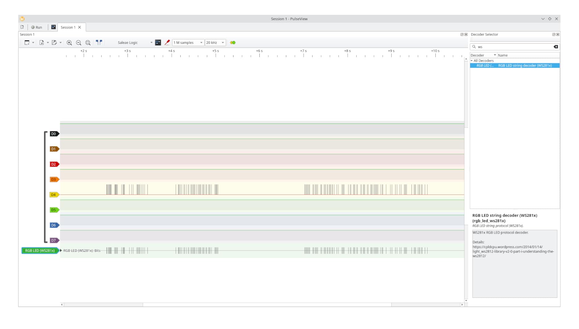
Download PulseView from sigrok for Windows, macOS or Linux. Then install the WinUSB driver for your device with Zadig, which is the step the fx2lafw firmware dependency makes necessary on many boards. This is the single most common install blocker, and it is also the only genuinely hard part of the whole process.
Step 2: wire the ground first, then the signals
Connect the ground lead to a ground pin on your circuit before anything else. Then map your channels: Ch0 to SDA and Ch1 to SCL for I2C, or Ch0 to MOSI, Ch1 to MISO, Ch2 to SCK and Ch3 to CS for SPI. Use proper test clips rather than loose grabbers, because a slipping contact looks identical to a real glitch.
Step 3: start with conservative settings
Set the sample rate to 8 MHz and the sample count to 1 million. That combination is fast enough to see 400kHz I2C comfortably and slow enough that a cheap streaming board will not drop samples. Press run, and you should see a repeating transaction on screen within a second.
Step 4: add the decoder and read the annotations
Choose the I2C decoder, assign SDA to channel 0 and SCL to channel 1, and the raw square waves become labelled addresses, bytes and acknowledgements. That step is the entire point of the instrument: once you can see the bus, debugging changes from guesswork into verification, which is the sentence every forum thread on this topic eventually arrives at.
6 Beginner Mistakes That Ruin Your First Capture
Every one of these produces a capture that looks like a broken circuit when the circuit is fine.
No common ground. Without a shared ground between the analyzer and the board under test, every reading is meaningless and can damage hardware.
Ignoring voltage limits. The entry-level boards here tolerate up to 5.25V and nothing more, and probing a 12V or mains-adjacent node will destroy them.
Wrong channel-to-pin mapping. Assigning SCL to the channel you labelled SDA produces a plausible-looking trace that decodes to nonsense.
Trusting the serial monitor. Firmware reports what it thinks it sent. Only the analyzer shows what actually went out on the wire, which is the only reliable way to find a dead bus.
Running 24 MHz on a streaming board. A busy PC causes dropped samples, and beginners read the gaps as a hardware fault. Drop to 8 MHz.
Assuming a decoder exists. Protocols such as custom 38kHz IR carriers have no stock decoder. Budget time for a custom decoder, or pick a platform with a deeper decoder library.
Frequently Asked Questions
What is the best logic analyzer?
For a beginner, the HiLetgo 8-channel 24MHz board is the best overall choice. It holds a 4.5 rating across 589 reviews, handles I2C, SPI and UART on the free PulseView software, and its 24 MHz sampling rate is roughly sixty times more headroom than a 400kHz I2C bus needs. Step up to the innomaker LA1010 when you need 16 channels, and to a buffered model like the DSLogic Plus when dropped samples start ruining your captures.
How to choose a logic analyzer?
Decide four factors in order. Channel count: 8 covers most hobby projects, 16 is comfortable for multi-peripheral debugging. Sample rate: buy for the bus, not the microcontroller, so 24 MHz is plenty for I2C, SPI and 115200 baud UART. Memory depth: hardware buffer memory protects captures from USB drops, streaming does not. Protocol decoders: check that the software supports the protocols you actually need, since decoding lives in the software rather than the hardware.
When to use logic analyzer vs oscilloscope?
Use a logic analyzer for digital data and protocol decode: I2C acknowledgements, SPI transfers, UART traffic, chip select timing. Use an oscilloscope for analog behaviour: power rail sags, ringing on an edge, clipping in an amplifier stage. If your project is mixed-signal, the Digilent Analog Discovery 3 covers both in one box, otherwise start with whichever question you are actually asking.
Is ad2 a logic analyzer?
The Digilent Analog Discovery 3 includes a logic analyzer. It is a USB oscilloscope, waveform generator, logic analyzer and variable power supply in one instrument, with 16 digital I/O channels at up to 125 MS per second that are individually configurable at 3.3V logic with 5V tolerant inputs, alongside two 14-bit 125 MS per second oscilloscope channels and programmable supplies.
What sample rate do I need for I2C?
For 100kHz and 400kHz I2C, a 24 MHz analyzer is more than sufficient, since Nyquist only requires sampling at twice the frequency of interest. Even a few megahertz works in practice. Owners of 24 MHz boards commonly report useful signal bandwidth in the low single-digit megahertz, which is still comfortable headroom. Spend on channels or on a hardware buffer instead of raw sample rate.
Bottom Line: Which Logic Analyzer Should You Buy?
Working through all eight, we landed on the HiLetgo 8-channel 24MHz board as the best logic analyzer for beginners in 2026 for one reason: it does the actual job. Its 589 reviews at 4.5 stars describe working captures on free software that beginners already use, and its 24 MHz ceiling is irrelevant to the buses beginners debug.
Move up to the innomaker LA1010 when you need 16 channels, and to the DSLogic Plus when your captures start losing samples and a hardware buffer becomes necessary. The Saleae Logic 8 and the Digilent instruments are excellent, and the wrong purchase for someone whose Serial Monitor still cannot tell them why a BME280 will not respond.
Clip on a ground lead, set 8 MHz, capture, and add a decoder. That sequence is the whole hobby.